What is PWM
What is PWM
PWM frequency:
It refers to the number of times the signal goes from high level to low level and back to high level within one second (one cycle).
In other words, it indicates how many PWM cycles there are in one second.
Unit: Hz
Notation: 50Hz, 100Hz
PWM period:
T = 1/f
Period = 1 / frequency
50Hz means a 20ms cycle
If the frequency is 50Hz, that is, one cycle is 20ms, then there are 50 PWM cycles in one second.
Duty cycle:
It is the ratio of the high - level time to the total cycle time within a pulse cycle.
Unit: % (0% - 100%)
Notation: 20%
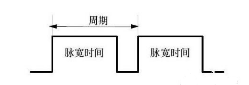
Cycle: The time of one pulse signal. The number of cycles measured in 1s is equal to the frequency.
Pulse width time: High - level time
In the above figure, the ratio of the pulse width time to the total cycle time is the duty cycle.
For example, if the cycle time is 10ms and the pulse width time is 8ms, then the low - level time is 2ms. The total duty cycle is 8/(8 + 2)=80%.
This is a pulse signal with a duty cycle of 80%.
As we know, PWM is Pulse Width Modulation. By adjusting the duty cycle, we can adjust the pulse width (pulse width time), and the frequency is the number of pulse signals within a unit of time. The higher the frequency,
Taking 20Hz with a duty cycle of 80% as an example, it means that 20 pulse signals are output within one second, and the high - level time for each is 40ms.
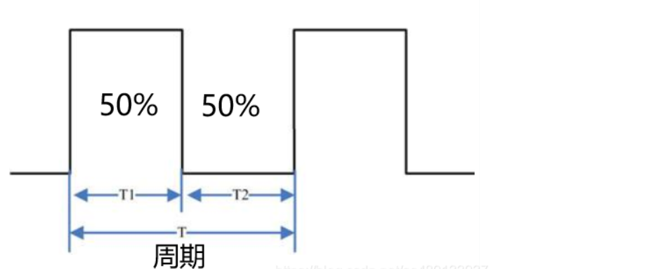
In the above figure, the cycle is T.
T1 is the high - level time.
T2 is the low - level time.
Assume the cycle T is 1s, then the frequency is 1Hz. The high - level time is 0.5s, the low - level time is 0.5s, and the total duty cycle is 0.5/1 = 50%.
PWM principle
Take a single - chip microcomputer as an example. We know that the IO port of a single - chip microcomputer outputs digital signals, and the IO port can only output high - level and low - level signals.
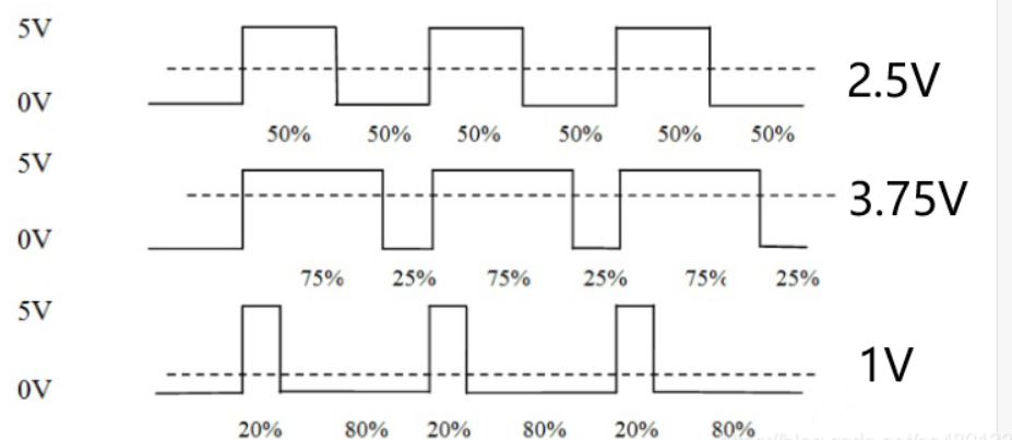
Assume the high - level is 5V and the low - level is 0V. Then, to output different analog voltages, we need to use PWM. By changing the duty cycle of the square wave output by the IO port, we can obtain an analog voltage signal simulated by a digital signal.
As we know, the voltage is applied to the analog load (such as an LED lamp, DC motor, etc.) in the form of a repeating pulse sequence of connection 1 or disconnection 0. Connection means DC power supply output, and disconnection means DC power supply disconnection. Theoretically, by controlling the connection and disconnection time, we can output an analog voltage of any value not greater than [sensitive word] voltage (i.e., any value between 0 - 5V).
For example, if the duty cycle is 50%, the high - level time and the low - level time are each half. At a certain frequency, we can get an analog output voltage of 2.5V. If the duty cycle is 75%, the obtained voltage is 3.75V.
The regulating effect of PWM comes from the control of the "duty cycle" width. When the "duty cycle" widens, the output energy increases, and the average voltage value obtained through the RC conversion circuit also rises. When the "duty cycle" narrows, the average voltage value of the output voltage signal decreases, and the average voltage value obtained through the RC conversion circuit also drops.
That is, at a certain frequency, different output analog voltages can be obtained through different duty cycles.
PWM realizes D/A conversion through this principle.
Summary:
PWM changes the effective output voltage by changing the duty cycle within a cycle at an appropriate signal frequency.
The higher the PWM frequency, the faster the response.
PWM control of motor speed
The duty cycle can be used to adjust the motor speed. We know that the duty cycle is the ratio of the high - level within a cycle. The larger the ratio of the high - level, the larger the duty cycle. For a DC motor, when the pin at the motor output end is at high - level, the motor can rotate. When the output end is at high - level, the motor starts to rotate and accelerates gradually. When the high - level suddenly changes to low - level, the motor will not stop due to the inductor's function of preventing current mutation and will maintain its original speed. Repeating this process, the motor speed is the average voltage value output within a cycle. So, essentially, when we adjust the speed, the motor is in a state of neither completely stopping nor fully rotating at full speed. The average speed within a cycle is the speed adjusted by the duty cycle.
In motor control, the higher the voltage, the faster the motor speed. By outputting different analog voltages through PWM, the motor can reach different output speeds.
Of course, in motor control, different motors have their suitable frequencies. If the frequency is too low, the movement will be unstable. If the frequency is just within the human ear's audible range, a whistling sound may sometimes be heard. Motors may not be able to respond if the frequency is too high.
Generally, the normal frequency range for motors is between 6 - 16kHz.
PWM control of servo motors
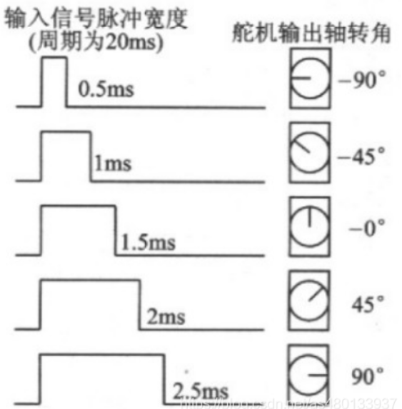
The control of a servo motor is achieved by applying a fixed frequency with different duty cycles to control the servo motor's different rotation angles.
The frequency of a servo motor is generally 50HZ, that is, a time - base pulse of about 20ms, and the high - level part of the pulse is generally in the range of 0.5ms - 2.5ms to control the servo motor's different rotation angles.
The 500 - 2500us high - level part of the PWM corresponds to controlling the 0 - 180 degrees of a 180 - degree servo motor.
Taking a 180 - degree angle servo as an example, the corresponding control relationship is as follows:
0.5ms--------------0 degrees;
1.0ms------------45 degrees;
1.5ms------------90 degrees;
2.0ms-----------135 degrees;
2.5ms-----------180 degrees;